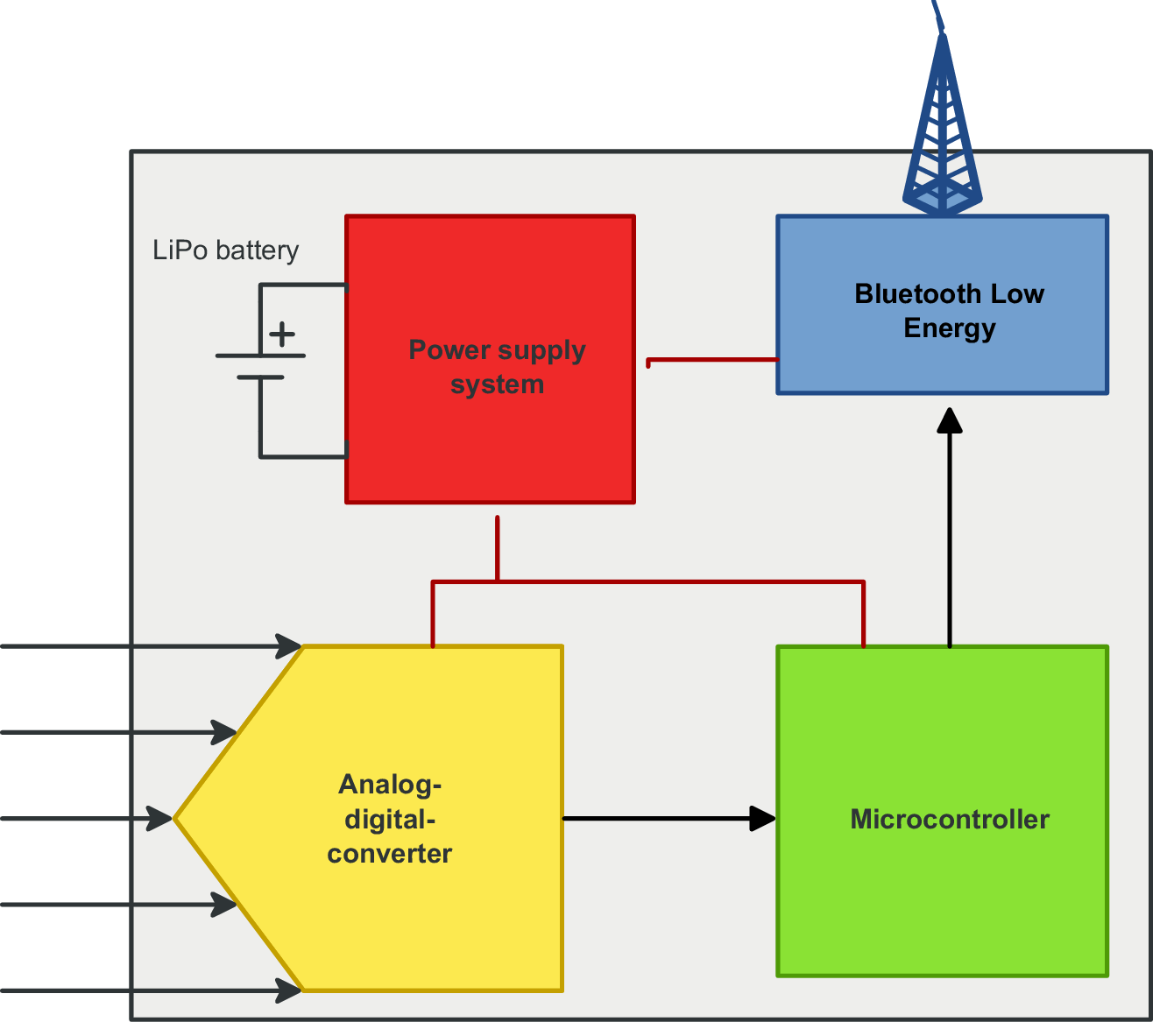
Fig. 1. System diagram.
Abstract A Bluetooth Low Energy connected EMG recording device is designed and tested. The system design is discussed in detail and the evaluation results for the prototype are presented. Finally possible future work is discussed and a conclusion is drawn.
Fig. 1. System diagram.
Using the motivational power of video games to get people to do fitness and exercise is a topic of ongoing research. The Serious Games Group at KOM (Multimedia Communications Lab) at Technische Universität Darmstadt is working on these so called exergames as part of their research on how to apply gaming technology in new application domains.[1]
For exergames it is essential to record the activity of the player, as it is used as input to the game. Although modern MEMS (micro-electromechanical systems) sensors allow to accurately determine the acceleration and orientation of a body in space, it is very difficult to distinguish between readings caused by the player’s movements from externally originated ones. An EMG (electromyography) device however enables the researchers to measure the actual muscular activity of the player. But there are drawbacks to this approach: commercial EMG systems are usually quite expensive and bulky. This makes them unsuitable for field-testing.
The task of this project is to design a cheap, compact and portable EMG system using off-the-shelf parts (see Fig. 1). The system communicates with a mobile phone using a wireless connection. To present the recorded EMG data to the user an Android App is created.
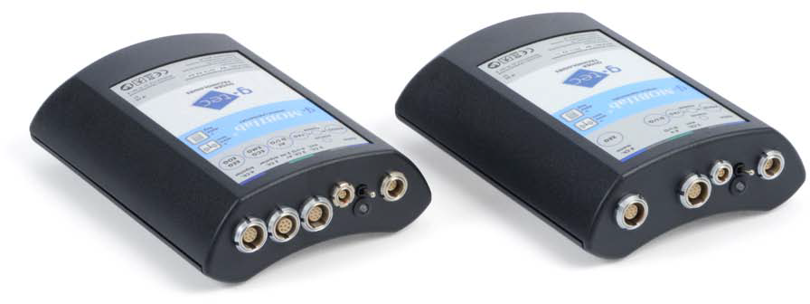
Fig. 2. g.tec g.MOBIlab+ biosignal acquisition system.1
Portable, research-grade EMG acquisition systems are available from several manufacturers. These come with up to 16 channels and the required medical certification. However they are designed to either talk to a custom receiver or a PC. Processing and evaluating the data with a mobile phone is not possible with these devices. Many of them are also bulky and their prohibitively high price makes a wider deployment impossible.
Electromyography is the study of muscle activity through the measurement of the electrical potential produced by them. It can be used either as a diagnostic tool or to analyze muscle movement (kinesiological EMG). Given the scope of this project the latter will be presented in detail.
For kinesiological EMG, usually three electrodes are used: two active electrodes and a reference electrode. The reference electrode is connected to electrically unrelated tissue and provides a common reference for the measurement. The two active electrodes are placed at two points of the muscle of interest to pickup the potential across it. They are connected to a difference amplifier which computes the difference of their values. This is to suppress noise and other unwanted signals common to both electrodes. Therefore an instrumentation amplifier is used.[2] After the signal was amplified and digitized it is usually necessary to apply digital-signal-processing before the signal can be presented to the researcher. This includes filtering, offset substraction and normalization of the amplitude.
For this project surface electrodes were used exclusively, as don’t need medical supervision when applied and cause minimal discomfort compared to inserted (needle) electrodes. However they have a lower bandwidth and can only be applied to surface muscles.[3]
Bluetooth low energy, also know as Bluetooth LE or Bluetooth Smart, is a recent wireless personal area network technology. Compared to “Classic” Bluetooth, it is intended to provide considerably reduced power consumption and cost. It is thought to enable new applications in the health-care, fitness and other industries. It is implemented in a growing range of mobile phones, most prominently all recent iPhones. Bluetooth low energy is not backward-compatible with the previous Classic Bluetooth protocol. It defines several profiles for certain applications, like for example devices that measure the heart rate. Bluetooth low energy operates in the same 2.4 GHz spectrum range as the Classic Bluetooth. As the name indicates, Bluetooth low energy has much lower power requirements compared to Classic Bluetooth (factor 2 to 100). However this comes at the price of a much lower maximum application throughput (0.27 Mbit/s max.).[4]
The reason why Bluetooth low energy was chosen for this project is its broad support in mobile operating systems and its low power consumption. It is also easily integrated in a project through the use of readily available, highly integrated modules.
The system design follows the partitioning shown in Figure ??. Each of the four major building blocks will in the following be presented in detail.
For the analog front end the Texas Instruments ADS1298 is used. It is a low-power, 8-channel, 24-bit analog front-end for biopotential measurements. It integrates 8 low-noise, high-resolution ADCs, 8 programmable gain amplifiers, an internal reference and on-board oscillator. It is perfectly suited for ECG, EEG and EMG applications. With sample rates of up to 32 kSPS it is capable of recording even the fastest muscle activities. It connects to the microcontroller via its SPI interface.
The Nordic Semiconductors nRF8001 is a single chip Bluetooth low energy solution. It integrates the complete radio interface and necessary control logic.Through an SPI serial interface it can be controlled by a microcontroller. The IC is available on pre-built and tested modules that ease system integration. It is also supported by libraries for the Arduino development environment.
The main processing unit of the device is the Teensy 3.1 microcontroller board by Paul Stoffregen. It comes with a powerful 32bit Cortex-M4 ARM microcontroller. The microcontroller runs at 72 MHz clock frequency and integrates 256 kB of flash memory and 64 kB of RAM. With its DMA feature it should be able to to acquire, compress and transfer the incoming data in real-time. The Teensy 3.1 is Arduino compatible and comes with a broad selection of ready-to-use libraries. The use of the Arduino IDE makes the code easily maintainable and extensible.
For a portable system the power supply architecture is an important part of the design, especially so if it includes sensitive analog circuitry. First of all the Lithium Polymer battery itself needs to be taken care of. These batteries do not handle over- or under-voltage conditions gracefully and can even catch fire when abused. As this device is going to be strapped to a player’s body the battery has to be handled with extra care. Therefore three layers of protection will be implemented.
The first is the protection circuitry that is directly connected to the battery. Many commercial batteries already come with this circuitry installed, so it is just a matter of specifying an adequate model. The second layer of protection is a Texas Instruments bq29700 battery protection IC. This IC disconnects the battery from the remaining circuit in case of an overcharge, overdischarge or overcurrent event. The last layer of protection is realized by the Texas Instruments bq24380 charger front-end protection IC. It disconnects the charge controller from an external power source in case of an overvoltage or overcurrent event. For the battery charge controller the Microchip MCP73811 was chosen, as it is easy to implement and readily available. From the 3.7V supplied by the battery three power supply voltages are generated. The digital power supply of 3.3V is supplied by the linear-regulator internal to the Teensy 3.1. Both the nRF8001 and the digital part of the ADS1298 are powered by this regulator.
However the analog part of the ADS1298 needs a bipolar power supply. The positive 2.5V rail is generated by a Texas Instruments TPS73201 low-noise LDO. For the negative rail the battery voltage is first inverted by an Texas Instruments LM2664 charge-pump converter and then stabilized by a Texas Instruments TPS72301 low-noise negative LDO. The bipolar power supply can be turned off by the microcontroller to save power when the device is shut down.
For the hardware part a 4-layer PCB was designed in EAGLE. Although the 4-layer board is more expensive than a 2-layer one, for this design the advantages of having two additional layers outweigh the price difference. First of all having more layers makes the layout of the circuit board easier and quicker. The designer does not have to worry about the ground connections as the one of the internal layers is reserved exclusively for a ground plane. This ensures low impedance ground connections at any point of the board. All additional power supply voltages are routed on the second internal layer, leaving the top and bottom layers for the actual signals. Together with a clear partition of the layout in a digital and an analog part this results in a low-noise, low EMI design.
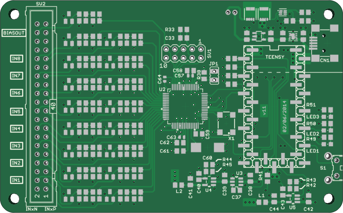
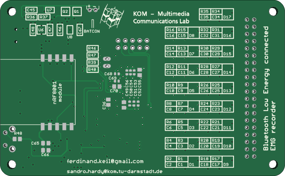
Fig. 3. 3D visualization of PCB design.
All channels of the ADS1298 are brought out to an 40 position, 2.54 mm pitch connector. Each channel has its own two-stage low-pass filter and ESD protection diodes. The design also incorporates three LEDs for status information and a push-button switch to turn the device on and off. The PCB measures 100 x 62 mm.
The firmware for the Teensy microcontroller board was developed using the Arduino IDE. The ADS1299 library by Conor Russomanno2 was used as the base for a custom library to support the ADS1298. The resulting library will be released after this project is completed.
Finding a suitable library for nRF8001 turned out to be more difficult. The reason being that most Arduino libraries are written for the original AVR microcontroller architecture and not 32bit ARM as the Teensy is using. Converting a library that use platform-dependent code would have been rather tedious and beyond the scope of this project. Therefore the Adafruit nRF8001 library3 that was converted to the Teensy platform by its creator, Paul Stoffregen, was chosen. It implements a UART-like connection over Bluetooth low energy and thus is easy to implement on the device side.
The actual firmware itself is just connecting the ADS1298 to the nRF8001: when a phone connects to the device it starts capturing analog readings and then transfers it via Bluetooth low energy. It also integrates power management functionality, powering down all circuitry when no connection is made and turning it back on when the button is pressed.
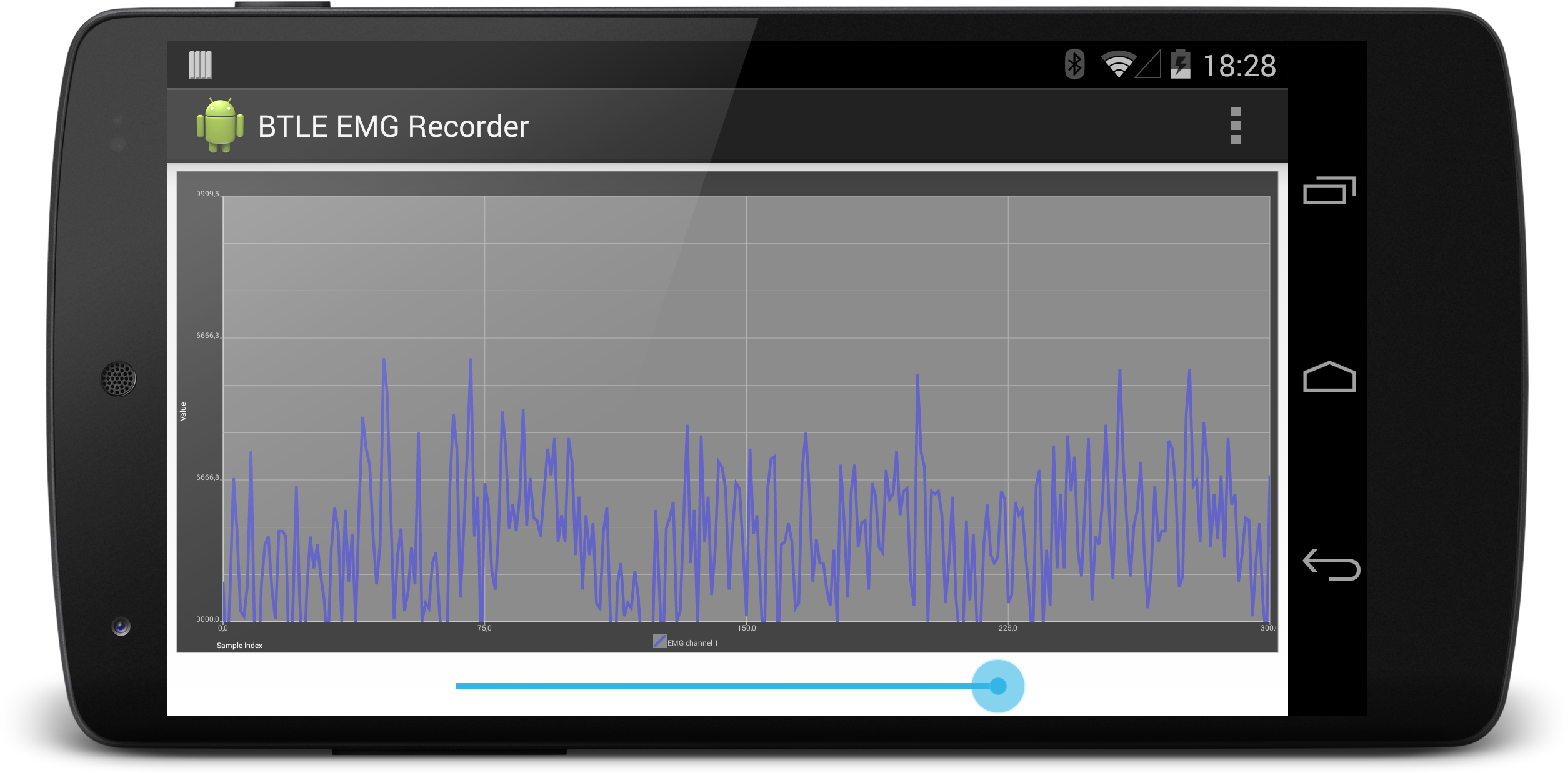
Fig. 4. Android App running on Nexus 5.
The Android App was built in Android Studio.. It relies heavily on Bluetooth low energy demonstration code by Tony Dicola4 and the Androidplot library5. When started it tries to connect to a nearby EMG adapter and when successful start displaying the readings of channel 1. As shown in Figure 4 it also offers a slider to apply variable gain to the signal. To keep the signal centered its offset is computed and subtracted.
Designing a complex device that incorporates mixed-signal circuit design, firmware and an App is a challenging task in itself. Delivering a working device in just six weeks even more so. Documenting every step of the design would be beyond the scope of this report, so in the following a few of the problems that arose during implementation will be described.
The firmware for the Teensy microcontroller was developed in two steps: first the part communicating with the ADS1298 was coded, then the nRF8001 was soldered on and its firmware was written. However when the development of the firmware for the nRF8001 started the module was found to not communicate with the microcontroller. After verifying the setup on a breadboard the problem was finally identified: the ADS1298, although in shutdown, was interfering with the SPI bus. This problem was solved by setting the pin controlling the ADS1298’ chip-select line to output mode and low.
When the firmwares for the ADS1298 and nRF8001 were brought together to create the final system, weird behavior could be observed. After the first value had been transmitted by the nRF8001 module the system stopped working. Specifically the microcontroller kept running but the SPI bus was not transferring data anymore. As the root cause for this the nRF8001 module was identified. Some commands for this IC consist of several SPI transactions. It does not release the bus before the command is not finished. However its library only does one transaction at a time and then has to be polled again. It is not possible to start communicating with the ADS1298 before the bus has been released. So in the main loop of the firmware a check was implemented that calls the polling function until the bus is released again. Afterwards that it continues communicating with the ADS1298.
These are examples for challenges that can arise during the development of a complex system. They show how the problem were solved and might give someone doing future work on a similar device some hints of where to look.
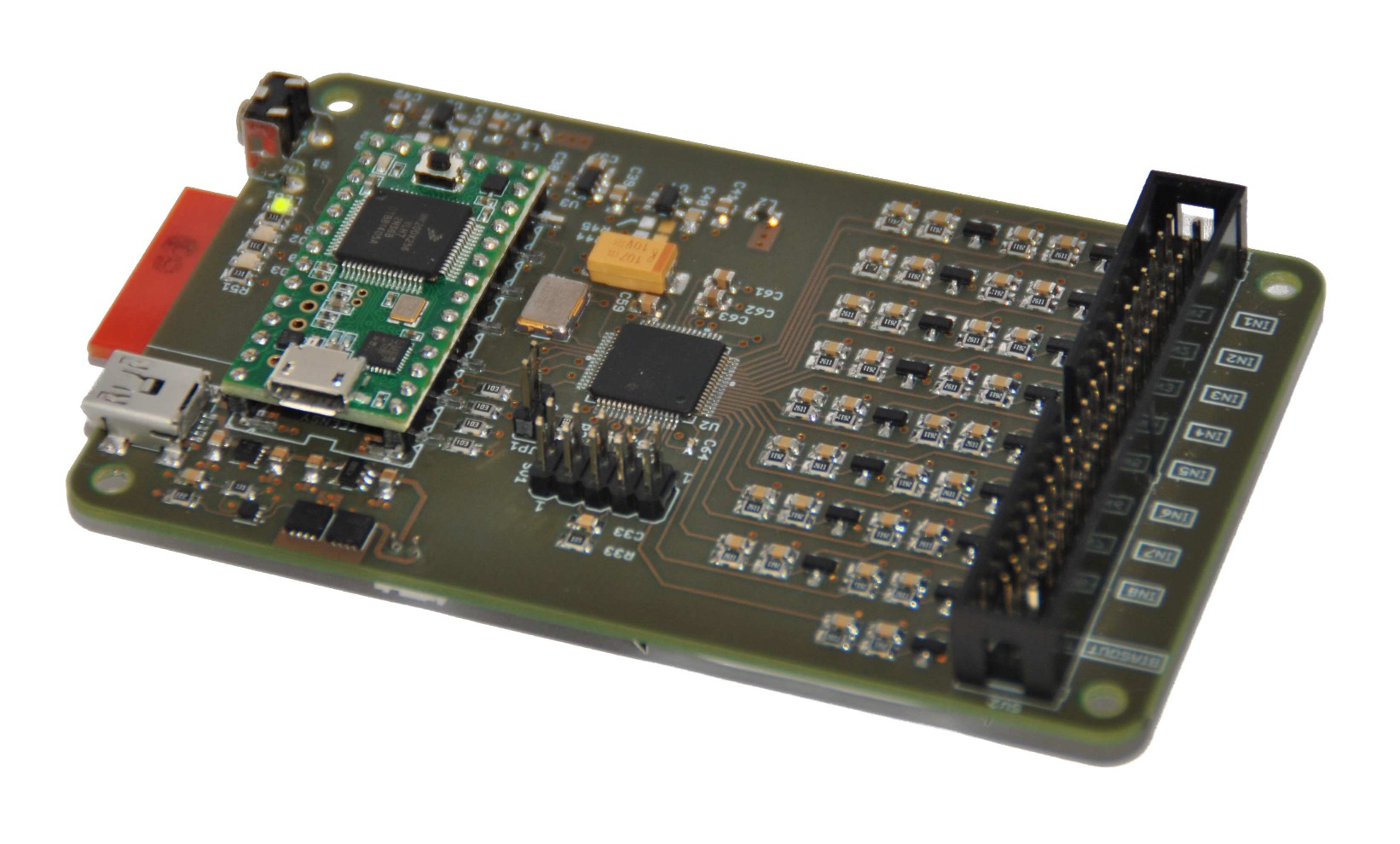
Fig. 5. The working device.
The resulting device is shown in Figure 5. Using the Android app data from channel 1 can be acquired at 250 samples/second. Using a gain of 12x the system has been tested with EMG and ECG signals. An example of an ECG recording is shown in Figure 6 and the typical waveform as known from heart monitors can be seen. The recording was made with the internal PGA set to a factor of 12x and an additional gain in the App of about 700 - that goes to show the very low noise floor of the device.
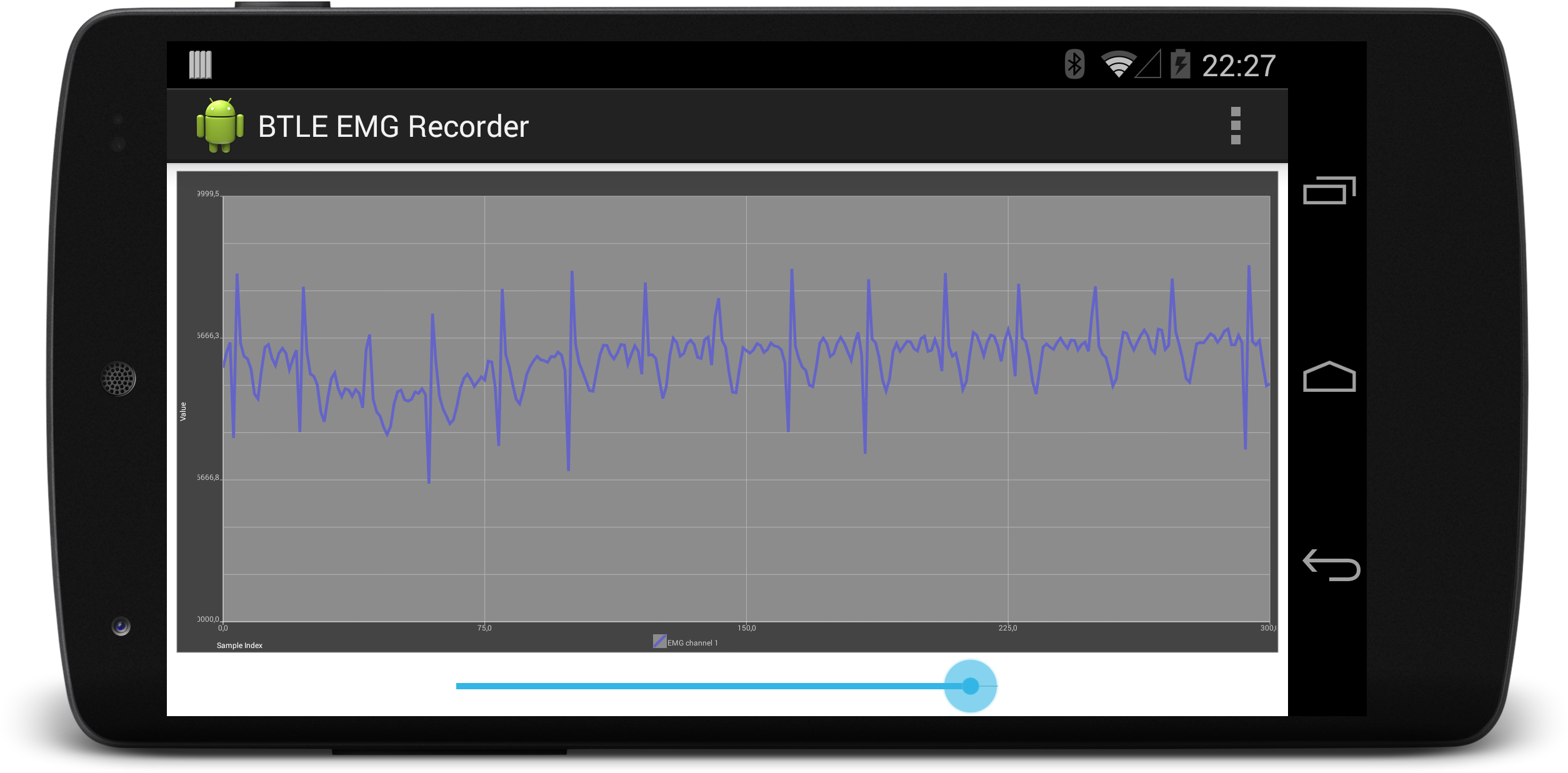
Fig. 6. Sample ECG recording.
The power consumption of the device was also measured and the results are shown below:
The used Lithium-Polymer battery had a capacity of 1400 mA h resulting in a theoretical standby time of about 8 days and a run time of one day. Using the integrated battery charger the battery can be charged to full capacity in about 4 hours.
Connecting the device to a computer via USB enabled much higher sample-rates. Using a Python script the signal can be recorded at a sample-rate of up to 4000 samples/second and written to a standard audio file. This file can be processed further using standard audio software like the open source Audacity. This is especially useful to apply filters, reduce noise or amplify the signal.
The goals that were set for this project were met. A working prototype was built and an App was written to demonstrate its capabilities. The firmware also implements all basic functionality and is easily extended using the library created for the ADS1298. However there is still a lot of room for improvements and additional features. These will be discussed in the following section.
This project was thought to implement a platform and its basic functionality so that future projects can build upon it. Possible features or improvements that could be implemented in the future are:
This project set out to implement a portable, battery-powered, Bluetooth Low Energy connected EMG recording device. This goal was achieved and a working prototype of the circuit was built and tested. Also an Android App and two Python script were written to demonstrate the capability of the device. Although there is still room for future work, the project was an overall success.